Virtualization
Digitalization is no longer a choice for businesses in line with the demands of their customers and the experiences of their employees with the rapidly developing technology. Most global businesses have started to use hybrid solutions that host cloud applications or cloud services in-house in order to expand the applications they use. It has been accepted that network devices can be delivered to the software safely with the transfer of servers to the virtual environment. Thus, the use of SDN technologies, which started to be developed in 2005, is becoming widespread and developing.
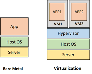
The development of technology has enabled the growth of data centers and has led to the increase of virtualization. Over time, cloud architectures have also become a need for network management. Cloud architecture pioneered the elimination of hardware dependency on the manufacturer for certain network devices. Software versions of many things such as computing, storage, and network applications are created with virtualization. The technology that makes virtualization possible and runs on a server is the Hypervisor, which is part of the software. It divides the physical resources owned according to the needs and allocates them for use in the virtual environment. Thus, with the hypervisor, it is possible to transform a physical server into virtual machines (VMs) with CPU, memory, and operating system.
In the data centers, a team with different competencies should be available For each group of network devices. Teams have different competencies for the devices and response zones they use. This increases the cost for businesses at the right rate. Thanks to the cloud architecture, different devices in the same cabinet can be gathered under a common roof and can be maintained as virtual machines. Thus, alternative solutions are created for demands that require less budget and competence and more budget. Network virtualization is performed by simulating hardware on software. At this point, there are three techniques used for network virtualization; SDN (Software Defined Networking), NFV (Network Functions Virtualization), and NV (Network Virtualization).
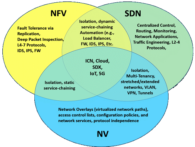
NFV controls network functions such as network address translation, firewall, intrusion detection, and specific protocols and applications rather than completely controlling a network. In this way, it allows different network operators to implement network policy regardless of the areas in which the services they offer within the network will be used and how the traffic will be routed through these services and protocols. Thus, it is aimed to virtualize all hardware resources, allowing it to grow without adding more devices to the network. Any organization can maximize efficiency while simplifying a wide range of network functions and delivering new revenue-generating services faster and easier than ever before with NFV. There is no specific communication protocol used for NFV. NFV applications can be implemented on all servers that comply with industry standards. In summary, NFV enables certain services and applications used in the network to be used by virtualizing them.
While both SDN and NFV make network architectures more flexible and dynamic, they play different roles in The main similarity between SDN and NFV is that they both use virtualization within the network. While SDN tries to separate network control functions from network routing functions, NFV tries to abstract the hardware it runs on from network routing and other network functions. Therefore, both are used to provide software abstraction of network design and infrastructure. SDN separates the Control and Data planes in the network architecture and is used by running on different devices. While SDN architecture focuses on data centers as usage areas, NFV targets internet service providers or operator companies in terms of working structure and usage area. Thus, almost all of the services offered can be virtualized. While both SDN and NFV make network architectures more flexible and dynamic, they play different roles in defining those architectures and the infrastructure they support. If SDN is used in an NFV infrastructure, packets in traffic are forwarded from one network device to another. Thus, while NFV provides basic network functions, SDN controls and regulates them for specific uses. For this reason, SDN and NFV technologies are complementary but independent of each other. The advantage of using SDN is that single hardware can support multiple virtual machines. A virtualized solution is more portable, scalable, and cost-effective. SDN controls the entire network. By using SDN in a data center, operators are given more control, centralizing the ever-increasing use of virtual machines to provide ease of use. In summary, the common feature of this architecture is that it reduces OPEX (Operational Expenditure) and CAPEX (Capital Expenditures / Start-up Cost) expenses and ensures that services are easily offered to users.
NV, on the other hand, allows the system to be controlled by virtualizing only a particular device. Hardware resources do not change, but the software or application used resides on another server in the network. Its main advantage is the automation that occurs in the network. NV is used when different networks are required within a virtual infrastructure. With NV, a group of servers on a company’s network containing important information can be virtualized and isolated, if desired. An additional hardware platform can support multiple virtual devices or machines that are easy to rotate up or down as needed. As a result, a virtualized solution is more portable, scalable, and cost-effective than any other.
Working Architechture
Software-Defined Network, namely SDN, is a structure that emerges with the theory of physical separation of Control Plane and Data Plane, which are together in the network architecture, and facilitates network management. SDN provides the ability to quickly and simply control and manage the behavior of end devices. Thus, the control and routing processes within the network are separated from each other.
With the separation of the transmission process performed on the Data Plane of the packets to be transmitted from the routing process performed on the Control Plane, the working structure of the network is centralized in a single network component called the controller. In this case, SDN, which examines the Control Plane as a different element from the network devices, ensures that all devices can be controlled through a single central interface or control panel. By providing an infrastructure-independent service, it allows a single device to have more than one controller, and a controller to remotely control thousands of end devices. This allows the elimination of hardware dependency on the manufacturer while supporting the use of logical network topologies.
SDN contains almost all of the technologies used in the network and enables structures with complex topology to be easily managed. Network devices communicate with each other over a common communication protocol and have centralized management independent of hardware. The services offered on the network with SDN can be easily implemented and instant status monitoring can be performed thanks to the graphical interface.
SDN technology mainly provides support for data centers and internet service providers. Because each service provider is free to create different network designs in the service they will provide to their customers. For this reason, the use of SDN is of great importance for areas where corporate internet infrastructure is used. Because the SDN working structure has a different structure from the network architecture used today. The traditional network model using MPLS was not designed to support cloud architecture. SDN provides easy detection and quick resolution of problems that may occur in traditional networks with complex topology without central management. It aims to improve the network performance and make the network structure programmable.
Working Structure of SDN
The working architecture of network devices used today consists of three planes. These are; The Control Plane, the Transmission Plane, and the Data Plane is defined. The Management Plane deals with the administrative decisions on the device and the transmission of packets received from the source to the destination. The Control Plane decides the point at which packets will be transmitted depending on the protocols running on the device. In addition, a routing table is maintained which is used to select the best route while providing transmission within the Control Plane. The Data Plane provides the transmission of data in line with the transmission decisions taken over the Control Plane.
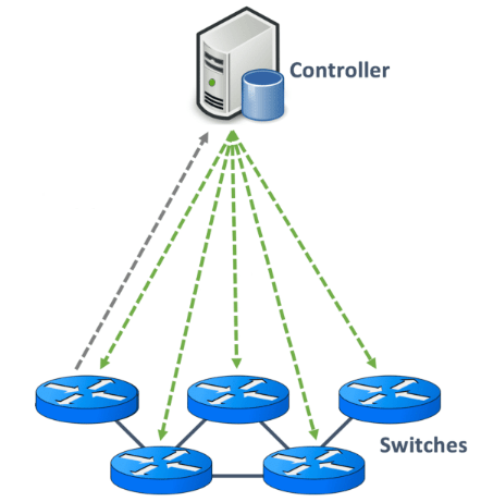
These “Control – Data – Management” layers are separated from each other in the working architecture of SDN devices. The basis of this structure is the separation of software and hardware-oriented concepts from each other. The main purpose of separating these two planes is to ensure that the network can be coded on an open interface. Control Plane and Management Plane functions are gathered on a central device called “Controller” and network control is logically centralized. The controller has all the information about the network and is in a position to evaluate in the light of the information it has. In addition, it provides the communication of devices gathered under certain groups or organizations and is responsible for the central management necessary for the active operation of all devices.
Network devices at the endpoints have only the Data Plane. Thus, the devices at the endpoints take packet forwarding decisions in line with the transmission information they receive from the controller. For this reason, in case of any software-related problem, the software is intervened from a single point and the system is kept alive. At this point, the tasks of network control and packet forwarding diverge. Thus, the system is freed from operating in a hardware-dependent structure and provides the isolation of the infrastructure service from applications and network services.
Network control becomes directly programmable as Routing and Control operations are separated. Network resources are configured, managed, optimized and network security is provided by using SDN programs in line with customer demands and needs of network administrators over time. As a result, traffic flow across the network can be adjusted dynamically, bringing together network design, installation, management, and operation. The risk of human error is minimized as the network configuration is compiled automatically.
SDN does not directly contact any of the technical issues that can be experienced in network traffic, such as congestion control, traffic engineering, security, mobility, or real-time communication. However, it opens up new opportunities to create and implement innovative solutions to these and similar problems. For example, it can filter for packets in network traffic, or it can generate alarms about the current situation in the network and automatically follow the alarms on the monitor screen. In addition, thanks to its dynamic working structure, it provides an environment suitable for the use of cloud architecture and supports the use of high bandwidth. In this way, it allows to serve simultaneously and in harmony with different programs or applications. That enables on-demand or automatic application sharing, meeting market needs cost-effectively, and minimizing infrastructure costs at the same time.
Thanks to the central management device, that is the controller used in SDN, information about all devices on the network can be listed and the topology of the entire network can be viewed. The current status of all physical interfaces on the network can be viewed instantly. Configuration changes can be made without interrupting operating systems, for example, a new VLAN can be added. In addition to the convenience of creating a new end device, it can be included in a certain network group through the controller, IP addresses can be given, routing and access lists can be configured automatically.
Hundreds of devices do not need to be configured individually, as all operations are performed through a single control panel. All devices assigned to a certain group can be configured via a common template or the same change can be applied to all devices via a script. It’s much easier to redesign the network architecture without having to rewire anything.
SDN network services and applications can run in a common software environment. In addition, the fact that network administrators can make software according to their own needs without relying on special software, dynamic, automated, able to configure network resources very quickly, easily managed and optimized, makes SDN technology more preferred in the market. When open standards are implemented, SDN simplifies network design and network operation because, instead of instructions, devices, and protocols, all control is provided by the system administrator and the SDN controller. Thus, the SDN architecture fosters a vendor-neutral ecosystem.
For this reason, it becomes possible to replace the structure with alternatives by installing a different SDN software desired on the box where any device is running. Exactly at this point, hardware services and software services are separated from each other. Thus, services and applications running on SDN technology are isolated from basic technologies and hardware that provide physical connection. However, in order for a system to work software-based, it must have API support. Applications interact with the central controller and network via multiple APIs running on the device, rather than hardware-dependent management interfaces. Thus, the entire system is managed through APIs written with certain software and enabling certain services to be provided. At this stage, it is necessary to examine a device working with SDN technology, assuming that it has two different interfaces. These; Southbound Interface and Northbound Interface.
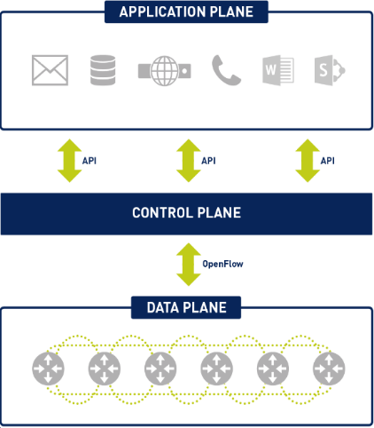
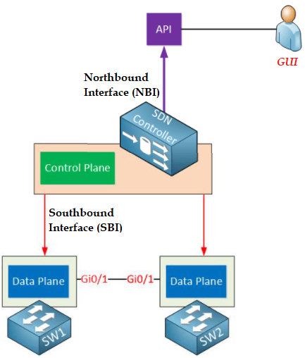
Southbound Interface: The controller, which is positioned as the central management unit in the SDN structure, must communicate with the network devices in order to program the Data Plane. These operations are implemented via the Southbound Interface. The Southbound Interface is not a physical interface or port, it usually appears as an API (Application Programming Interface). API is a software interface that enables an application to work in harmony by providing access to other applications using predefined functions and data structures. In this way, information about each other is transferred to the controller and routers. (OpenFlow, Netconf)
Northbound Interface: That is used in a network established with SDN structure, to access the controlling device located at the central point, so that the network administrator can configure on the controller or receive information about the transmission from the controller. These operations can be done via a GUI, but it also provides an API that allows other applications to access the SDN controller. This state is used to create configurations and automate network management. This communicates with applications running on the network to help network administrators shape traffic and deliver the services used.
At this point, due to the SDN working structure, OpenFlow protocol is used in communication. The OpenFlow protocol is a fundamental element for building SDN solutions. The OpenFlow communication protocol is the core element of the software-based network (SDN) architecture, based on open standards, which separates Control and Routing functions within the network. OpenFlow is a solution developed to eliminate all the deficiencies in the system and provides communication between the SDN controller and end devices. It plays a role in making the network structure more dynamic, easily manageable, and scalable. The word flow means a series of unidirectional flowing packets separated by the same source IP, destination IP, source port, destination port, forwarding protocols, and a configurable timeout. Virtualization is the most important element for the OpenFlow working structure. Thanks to virtualization, many technologies operate in isolation from the physical layer within the network, such as VPN, VLAN (IEEE 802.1Q), MPLS, Frame Relay, and even ATM. Programmable networks and network virtualization are technologies that can help solve problems without straining network traffic and bandwidth.
OpenFlow
Communication with networks, is a critical element for businesses, for any downtime significantly impacts business operations. OpenFlow defines both the communication protocol between the Data Plane and the Control Plane in the SDN operating architecture and part of the Data Plane behavior at the endpoints. OpenFlow allows network administrators to segment telecommunication networks by programming network devices accordingly. OpenFlow communication protocol is installed and configured on platforms with UNIX/Linux operating system.
OpenFlow protocol is not the first communication protocol to be studied during the development of the software-based network, but it has been the protocol that has attracted the most attention and provided the most efficient communication. One of the first methods used to separate the planes that form the basis of the network architecture is a low-budget card called NetFPGA. This product includes a programmable FPGA component, but its journey did not last long as the development was not clear enough. In addition to OpenFlow, ForCES protocols in GSMP and IETF were also included in the studies. At this point, OpenFlow has been chosen as the most appropriate set of rules that define how the communication between the devices on the Data Plane and the Control Plane should be carried out for which situations. It was first developed by researchers at Stanford University in 2008. Then, in 2011-2012, it was first used by Google in backbone networks. It is currently overseen and managed by the Open Networking Foundation (ONF).
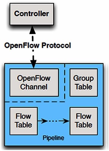
The core component of the OpenFlow system always includes an OpenFlow controller that communicates with one or more OpenFlow end devices. So in OpenFlow protocol, Control Plane and Data Plane are run on different devices. Thus, certain message formats are defined to enable communication between the controller (Control Plane) and the end device (Data Plane). The main function of the OpenFlow protocol is to receive packets arriving at a port and transmit them after examining them in the flow table on the controller. In this way, the devices on the Data Plane are not obliged to decide on which ways to go to the address where the packets coming to them will be forwarded, like the classical network devices used in the traditional structure. This responsibility belongs to the central controller on the Control Plane and the decisions taken are transmitted to the devices on the Data Plane.
The ports of the network device and the rules responsible for packet transmission are managed from a single point by disabling standard network protocols. A single configuration becomes available for multiple devices via a central interface, without the need for the network administrator to configure the network devices separately in this way. OpenFlow does not directly interfere with the behavior of the controller. Network traffic monitoring, packet prioritization, communication restriction, or decisions to be taken for certain updates are made via OpenFlow through the controller.
OpenFlow provides direct communication over the TCP protocol with the IANA-approved default port 6653. It can also communicate using a protocol such as TLS (Transport Layer Security) instead of TCP connection to ensure the security of communication. Here, the controller and end devices must have the appropriate certificates for a successful TLS connection. At this stage, there must be an IP connection between the controller and the end devices.
OpenFlow works by using the function of matching the data on the packet with the flow table in the controller for packet forwarding of the end devices. These operations do not cause any changes in the configurations on the devices. Thus, when a packet arrives at the end device, it looks at the flow table and checks for a match. According to the data in the flow table, which operation will be performed in the transmission is decided by the controller. These decisions are; decisions such as forwarding the packet from one port to another port (interface), forcing the packet to drop, or forcing the packet to transmit over the specified interface. Thus, the best effort is made on the shortest transmission path currently used. This ensures the protection of the packages in the traffic, even in the traffic that may experience congestion. Also, the smaller the packet size to be transmitted, the higher the load on the CPU creating the bottleneck. Both routing and OpenFlow perform well, if not for the small packet size, that can almost match the payload served. In summary, OpenFlow only updates the flow tables that define the path of a packet to be transmitted from the source to the destination, and by looking at the tables, it is decided by the controller and helps the packet to be transmitted by the end devices.
The Data Plane to keep the results obtained for all possible packet transmission addresses due to the capacity problem, a certain number of results are kept in the tables since it is not possible for the devices on. Incoming packets for transmission are compared with the results previously prepared on the flow table, called the OpenFlow table. The comparison starts from the beginning of the table and continues to the end of the table even if there is a match. As a result of the comparison process, if there is a match between the data on the table and the calculated data, the incoming packet is transmitted by referring to the transmission information written in the table. If more than one match emerges among the information held in the table when the table is scanned completely for comparison, which match is selected depends on the priority value of the data registered in the table. Among the information recorded in the OpenFlow flow table, the one with the highest priority value is processed. If there is no match between the data on the table and the calculated data, the devices on the Data Plane are notified that there is a packet with new transmission information on the Control Plane. Accordingly, the Control Plane performs the necessary operations for transmission, and the result is recorded in the OpenFlow table to be encountered again, and the packet is transmitted to the Data Plane for transmission.
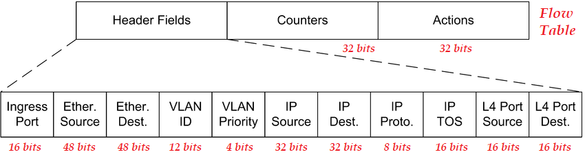
The OpenFlow protocol collects information such as packets received, packets sent, certain changes applied, statistics collected through messages that provide connection and exchange between the devices in which it is used. Routing tables are dynamically forwarded to the end devices by the controller. The controller can control many end devices simultaneously. OpenFlow provides a unique advantage in designing and programming the controller to create different routing tables for different flows. The information and dimensions in the OpenFlow package header are given in the image below.
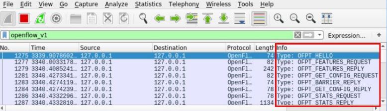
The controller and end device connection is established only after a successful TCP connection (3-way-handshake). End devices send a “HELLO” packet to the controller to initiate communication. This action is triggered by a script activated on the end device. The controller responds to the “HELLO” message and negotiates the OpenFlow version used. When an agreement is reached on the OpenFlow version used, the controller sends a “FEATURE_REQUEST” message. This message shows the number of OpenFlow flow tables supported, actions supported, etc. asks. End devices respond with a “FEATURE_REPLY” indicating all responses along with its unique identifier or DPID (Datapath ID). Thus, the OpenFlow protocol is successfully established between the end device and the controller. Since this is the only way for an end device to communicate with a controller, the connection established between the controller and the end device is of great importance.
If there is a situation where the requested information is missing or the requested information cannot be provided, the end device sends the “TABLE_MISS” response as a response. When the controller receives the “TABLE_MISS” packet from an end device, it sends it to the application running in the application layer. Informs the controller whether a new stream needs to be added to the flow table of the end device that is processing the packet. In such a case, the controller adds flow data about the end device to the OpenFlow flow table so that forwarding can be achieved.
OpenFlow flowchart consists of 3 basic components;
- Package Header
- Packet Handling Method (Action)
- Statistics with Flow packets size, tracking, and timeout data
OpenFlow tables are a series of unidirectional packets containing information such as source IP address, destination IP address, source port, destination port. There are two different types of devices that work with OpenFlow flow charts. The first is hardware-based devices that typically use TCAM (Ternary Content-Addressable Memory) and a proprietary operating system to implement the OpenFlow protocol. The second is software-based devices that use UNIX/Linux systems to implement the OpenFlow protocol. In terms of CAM working structure, it is generally defined as the opposite of RAM structure. Thus, OpenFlow tables created in the controller and the end device have a different structure from each other.
Two separate flow tables are managed on devices using software-based OpenFlow. The first is called a linear table and uses wildcards in packet header fields to match packets with streams. It defines only some characters for a flow within the record in the table, such as MAC address, IP address, and Port.
The second table is a complete comparison table and uses the HASH algorithm to store the entries of this record and can compare and search in them. The device with OpenFlow technology compares the header fields in this table with the header fields of the incoming flow. The size of the second table is 131072 full comparative flow entries. Full comparative input, on the other hand, covers all possible contents of a stream. The recorded flow content includes information such as the packet’s entry port, source, and destination MAC addresses, ethernet protocol, source and destination IP address, network protocol, source, and destination port.
What is SD-WAN (Software Defined – Wide Area Network) ?
Network administrators of corporations have difficulty in managing and controlling corporate and complex traditional networks. Developing technology has led to the use of corporate applications used in businesses by moving them to the cloud environment in order to reduce the workload of network administrators. In addition, the use of multi-cloud connections has increased with the increase in mobile internet needs of individual users. In this context, the demand for access to applications at any time and from any point is increasing. SD-WAN technology can be used to solve security vulnerabilities, heavy traffic, and similar problems during the transition from a traditional structure to cloud systems. This enables organizations to migrate to cloud applications with faster, more secure, and high-quality communication. Therefore, SD-WAN presents an attractive opportunity for both large topology enterprises and service providers to meet critical challenges.
More than one user and devices from multiple locations connect directly to cloud data centers with SD-WAN solutions. In addition, SD-WAN supports hybrid fabrics and multi-cloud systems to cost-effectively improve bandwidth availability and application performance. In this way, low-cost broadband usage and mobile applications are used in harmony with existing communications, resulting in lower WAN costs.
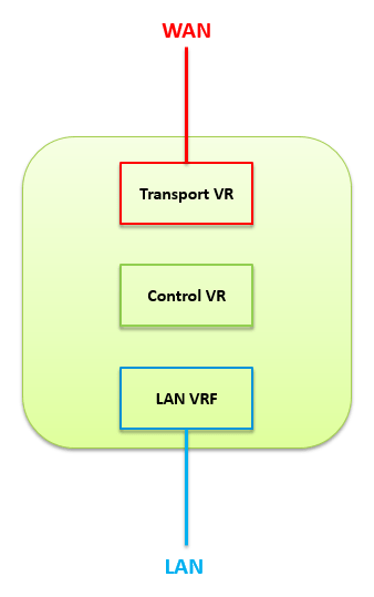
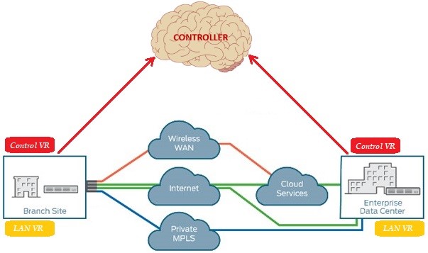
Software-defined wide area network (SD-WAN) is a special application of SDN technology, as well as being the whole of wide-area network services that are installed, configured, monitored, and secured by a controller placed at the central point. It provides an advantage over the traditional hardware-based network. Which is automates the control and management of enterprises, allowing a hybrid WAN service to be optimized for specific applications. Thus, endpoints can be easily controlled, managed, and commissioned in a simple and fast way via the centrally located controller. All the services it offers, including branches and centers, are built on the basis of WAN connections. Thanks to the Control Plane and the Data Plane, which are separated from each other within the SD-WAN architecture, the network specialists who manage the system provide remote access to the device without the need to go to the region where the device is located to manage the device and direct the device with centralized applications or rule-based interventions. The separation of planes in the architecture limits the damage that can be taken in a possible attack.
SD-WAN technology works simultaneously with multiple WAN connections (xDSL, MPLS, LTE, and Fiber) to ensure redundancy with open and software-based technology as much as possible, to provide uninterrupted WAN access with high quality, flexible, secure, and simple cloud features. It abstracts traffic management from hardware-dependent network structures. With the service provided, it supports multiple connection types, dynamically selects the transmission path for traffic, ensures that all management and installation stages are carried out through an easy-to-use interface, and allows VPN structures to work properly. Different internet services from internet service providers make different technologies available simultaneously or in a redundant manner. Thus, the network is abstracted and the single ISP dependency is removed for the services to work. It enables high availability and uninterrupted connectivity. Network automation is provided and endpoints can be automatically deployed remotely. Providing the user with a single WAN connection or VPN service, both protect data and secure it by using IP-SEC encryption. Thus, with a single internet connection or VPN offered to the user, it both protects data and decrypts it with IPsec encryption.
In addition, SD-WAN devices constantly monitor the health of each WAN connection connected to them and keep a record of the data it receives. In the event of an outage or traffic congestion on one of the WAN links, transmission calculations are performed quickly and traffic is redirected. Thus, with SD-WAN, fast and easy solutions are offered to endpoints that need more access and speed.
SD-WAN has been developed by taking inspiration from PFR (Performance Routing) technology in the historical past. PFR provides control of the intelligent communication path for application-aware routing across the WAN. The PFR is dynamically controlling packet forwarding decisions by looking at the application type, performance, policies, and the instantaneous traffic status of the route for transmission. Balances traffic over the best-performing path based on application policy.
DIA (Direct Internet Access), is the technology that enables the traffic passing over the devices located at the endpoints to be accessed directly to the internet without being directed to the center if desired, it enables applications or addresses that do not need internet access through the center to access the internet directly. Thus, frequent bottlenecks and delays in internet traffic going to the center are reduced, thereby balancing the load in the traffic and providing packet transmission.
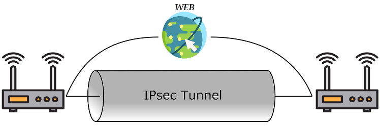
The main advantage of SD-WAN architecture is that communication is provided securely, end-to-end encrypted to secure packet traffic. The communication between the branches from the head office is secure, as well as the communication with the cloud. Since the packets transmitted in the communication are completely encrypted, no external user, including the internet service provider, can view the packet content in the flowing traffic. For instance, where applications access the hub directly through the branch office, traffic from a branch office is transported to the hub over the same IPSec tunnel without any isolation. Thus, communication is securely encrypted over IPsec tunneling, but this can negatively affect bandwidth.
In addition, thanks to the automatically installed DMVPN structure, the branches operate independently from the center and as if they are directly connected to each other. SDN architectures often use VxLAN (Virtual Extensible LAN) tunneling extensively. However, over time, alternative tunneling technologies such as NVGRE (Network Virtualization using Generic Routing Encapsulation) and DMVPN (Dynamic Multipoint Virtual Private Network) have been added to this structure.
Thanks to its deep packet inspection (DPI – Deep Packet Inspection) capabilities, it provides application recognition and application-based traffic management. With these advantages, network administrators solve the problems that occur in the system faster and at a lower cost. In short, the SD-WAN solution can be considered as a do-it-yourself approach where users install and manage the software, applications, and services they will use. In this way, the manufacturers or internet service providers that offer the service only take responsibility for installation, update and support services within the SD-WAN. Thus, any remaining application-based rules or specific redirects can be managed and controlled by the customer. With the network being programmable, it offers a structure that is open to development without waiting for a patch or update from the manufacturer. In today’s technology, it is seen as the ideal choice for businesses that want to get maximum efficiency from the infrastructure and want to monitor the branch traffic in detail.
In the configuration of SD-WAN devices, rules can be written based on IP addresses in a structure similar to Access-List, and it is possible to use application-based rules and special routes for packet transmission in a more practical way, suitable for cloud technologies. Thanks to the DPI feature on the devices, applications can be easily distinguished and detected. Thus, SLA-based criteria can be determined for the applications used and it can be prioritized over which line the traffic should be sent. Thus, it creates a control and management area from Layer 1 to Layer 7 in packet transmission. It allows the creation of a structure independent of the MPLS structure in the lower layer, just as it creates a private MPLS network. Also, if it is desired to make forwarding decisions dynamically, which path offers the best performance for a given application is determined by the controller by looking at the analytical data, and traffic is routed to the ideal WAN path.
In addition, SD-WAN technology includes certain analytical capabilities to monitor cloud applications and network performance. It has a structure that can learn thanks to application-based traffic engineering and artificial intelligence. It is critical for optimizing and automating network performance through inspections of traffic. In this way, it provides advanced monitoring, tracking, real-time traffic management, and instant status reporting services by monitoring network performance and recording packet traffic. However, the analysis capability may differ between different devices from different manufacturers. Users should choose the right deployment model based on their current network requirements and resources.
In addition, SD-WAN technology is increasingly seen as an important solution to meet these requirements, as the IoT infrastructure needs a complex and scalable structure. In addition, the digital transformation, which has been adopted by global organizations, allows the use of IoT technologies and applications. IoT applications require the ability to collect real-time data from multiple sources with real-time analytics to improve business performance. At this stage, IoT devices are used to distribute data, collect data, store data and manage the stored data. The traditional MPLS-based architecture, which is still frequently used today, does not support the scalability or flexibility required for the smooth operation of IoT devices. Cloud and IoT applications and the fact that voice and video communication has become a part of our lives, the need for more reliable and high-performance network structures is increasing day by day With the acceleration of the transition.
For example, modern applications such as VoIP calls, video conferencing, and virtualized applications require low latency to provide quality service. Congestion, packet delay, variation, packet loss, and service interruptions that may occur within the network adversely affect customer experiences. Featuring smart routing, SD-WAN optimizes performance for tools such as online video streaming and automatically prioritizes bandwidth in traffic based on application needs.
When there is a high demand for access to a business over the network, the connection capacity can automatically expand or burst capacity can be met. With the advantages it provides, it adds flexibility, redundancy, adequacy, innovation, agility, efficiency, and scalability to the network structure. The need for personnel that requires manual configuration and on-site intervention is reduced, and it provides centralized management in branch networks thanks to its manageability with a graphical interface. It enables the simple, safe, and fast deployment of new applications and services. In this way, it offers the opportunity to minimize network costs in the face of rapidly growing data traffic and helps higher bandwidth usage.
Overlay – Underlay
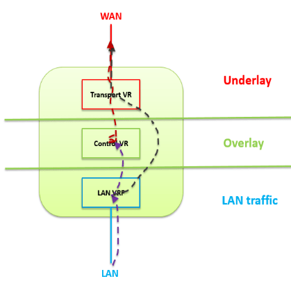
Network devices running on traditional architecture perform hardware-centric packet forwarding based on the destination IP address. At this stage, the end devices are responsible for packet transmission, and in transmission, the devices decide independently of each other based on address. This causes certain disadvantages and inefficient transmission processes. For example, a change in the network design may require hardware interactions, it is difficult to scale and virtualization is not possible. For this reason, in software-defined networks, both the Underlay and Overlay design are created and applied together so that the Control Plane and Data Plane, which are separated from each other in the working structure of the network, can be used efficiently.
Underlay network is the network layer (Routing, Switching, VLAN) where the physical network topology is located and traditional protocols work. Traditional technologies and protocols that work on Underlay, depending on the physical topology, work through the hardware and hardware-specific connections of the devices. For this reason, the biggest responsibility of the Underlay network is to provide IP accessibility and physical IP routing between points. For this, the devices in the network have to provide IP accessibility and perform packet transmission using a routing protocol. Routing protocols used in devices can be OSPF, IS-IS, BGP. The traffic proceeding by seeing all trace steps of the packet transmitted from one point to another in the network describes the Underlay structure.
NOTE: It is not possible to set up an Overlay network without an Underlay network. Thus, the Underlay network is the layer where the Overlay network components begin to be built.
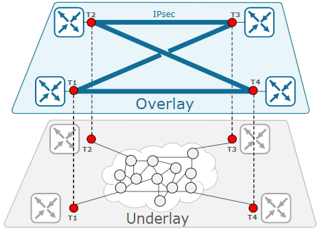
The overlay network is a layer that covers the protocols (VxLAN, VPLS, GRE, IPsec) used to establish private connections or tunnels, virtualize the network, and complete communication on the Underlay network, on the layer where physical transmission is provided through routing. It enables the use of tunneling and encapsulation technologies, providing both a faster and more reliable service. The logical layer, Overlay, works on a software basis. The main purpose of using an overlay network is to operate different structures efficiently by creating different virtual layers within the network. The routing decisions to be made at this stage are made with the help of software running on the protocols used.
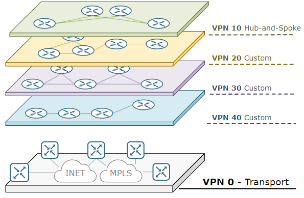
Thus, more than one Overlay design can be created depending on the area where it will be used on an Underlay network. For example, on Overlay, the network can be divided into different network layers, allowing the use of different VPNs. The VPN structures thus established are known only to the Overlay design. Underlay just follows standard IP routing.
OMP – Overlay Management Protocol
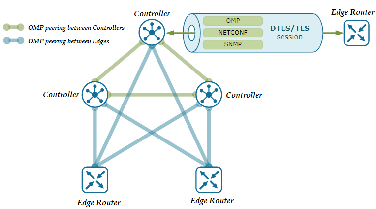
In order to facilitate the management of devices running on the Overlay network, some manufacturers use the Overlay Management Protocol within SD-WAN technology. OMP is a TCP-based proprietary Control Plane protocol used for the transmission and distribution of routing, rule, and management-based information between controller devices and endpoint-located routers on the Overlay network.
OMP is a protocol responsible for setting up and maintaining the Control Plane correctly. Overlay takes part in the regular operation of network communication, including the connections between the end devices in the network, the services provided, and the tunnels used. Manufacturers running the Overlay Management Protocol have OMP enabled on their devices by default, so no additional configuration or activation is required after the controller and edge devices are installed. OMP-powered devices automatically initiate OMP peering sessions among themselves, and the two endpoints of the OMP session are the system IP addresses of the two connecting devices.
OMP works inside control plane connections via DTLS session and establishes a peering relationship between devices. In the absence of a centrally located controller, OMP will not work between end devices. It works in a structure similar to the “Route-Reflector” structure that works in BGP. Devices connecting with each other perform authentication of each other and establish DTLS or TLS tunnels. Thus, OMP protocol mapping is created on the IP addresses of the connected devices, and the exchange of routing information takes place and helps to extract the network topology. As a result, it works much more efficiently than traditional routing protocols.
OMP is can be defined as the heart of the routing solution in SD-WAN Overlay networks. Because topology information is learned through OMP, working principles used for WAN are determined and information is exchanged for security keys. It assists the coupling between the centrally located controller and the end devices. It also enables to make decisions about the Path Selection in the routing to be performed between the devices. Thus, the load of the OpenFlow protocol is lightened. If the route information is determined by the OMP, the Administrative Distance value for the OMP is defined as 250 by Cisco manufacturers. If it is a Cisco SD-WAN technology, this value is accepted as 251. Regardless of the routes run, when the selections are made by OMP, they are displayed as OMP in the tables and local routes are kept in the OMP table. For this reason, there are three types of routes within the OMP:
- OMP Route (Examples of the network design and extracts the topology.)
- TLOC Route (Represents the endpoint of Data Plane Tunnels.)
- Service Route (for previewing different services (Firewall, Load Balancer, etc.)).
The route selection mechanism within the OMP works in the following order:
- At first, the OMP Route should be valid. This means the TLOC (or Next-Hop) must be valid and have an active BFD session. If an OMP Route is not valid, it will not be considered in Best Path Selection.
- The endpoint located device prefers to use the routing protocol running on it versus a route learned by the Controller device.
- Administrative Distance values are compared and the route with the lower AD value is preferred.
- If AD values are the same, higher value OMP routing is preferred.
- In this step, TLOC Preference is selected as the higher OMP route.
uCPE ve vCPE
The terms uCPE (Universal Customer Premises Equipment) and vCPE (Virtual Customer Premises Equipment) are common terms today.
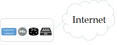
A traditional CPE is a physical machine located in an enterprise data center. It is the end device placed at the customer’s location for any service provided to the customer in the telecommunication world, and it can be used as a telephone, router, PBX, IPS, etc. can be defined as a special device such as In the data center, a certain area is needed in the data center for the management of different devices, electrical power and operation of the devices. Also, in a transmission, the packet must pass through each device individually and be processed. Structures that work in this way are not recommended today because they are not efficient, but rather costly.
Virtual CPE or vCPE was developed as a solution to the problems experienced on the physical CPE side. It is possible to operate the device in the cloud thanks to NFV without the need to locate a physical device in the customer’s data center. Thus, any CPE functionality required for the customer, such as routing, firewall, IPS, can be provided virtually from a single point, over a data center, without the need to invest, manage and use multiple devices. In this way, devices can be accessed remotely thanks to virtual machines and they can be used without any problems as if they were physical devices.
Devices called uCPEs are usually located in the customer’s data center or endpoint, but can also be located in a virtual different data center from the customer’s location if desired. It contains an application and software that enables it to take action in line with the information or decisions it receives from the controller device located at another point. These applications may have other functions such as routing, filtering, or security.
It has been realized that there is no need for a special physical device for the applicability of SD-WAN technology. In this case, SD-WAN is run as software in any box on the endpoints. Run it as an application on a virtual server in the central controller. All applications that will run on SD-WAN can be run in the virtual machine as an application in a similar way. Thanks to the API used, applications and devices are communicated with each other. In this way, the box of the device to be used at the endpoints does not belong to a single company and can contain more than one application or service, depending on the software inside. Thus, this box is called a universal CPE and the concept of uCPE (Universal) is created.
Applications can reside not only in the service provider’s data center, but also in the public cloud, SAAS cloud, or private cloud. Thanks to the software used in the device, all applications offered by uCPE can run anywhere and therefore have a more flexible usage structure. So the universal CPE is nothing but a server or white box capable of running multiple virtual functions. At this stage, the focus for SD-WAN is the ports provided between the client edge and the cloud, while the focus of virtual CPE is mainly on “virtual functions” such as IPS, filtering, firewall, routing.
What is SASE? (Secure Access Service Edge)
SD-WAN technology allows users to connect directly to the cloud bypassing the hub in many cases. However, this alone is not seen as an adequate solution. SASE provides a way for businesses to forward traffic from the cloud to endpoints, providing secure direct access to the cloud, without having advanced security tools at the endpoints. Thus, security is provided on the cloud itself.
The connectivity and security are provided at the endpoint, but with SASE, the only function needed at the endpoint is the SD-WAN router with using that SD-WAN technology. In this way, all security services are moved into the SASE cloud. Therefore, when SASE is used with SD-WAN, it is considered a combination that enables communication in the network and provides network security services. When the main functions on the SASE side are moved to the cloud, all that needs to be done at the endpoint is a simple SD-WAN box with connectivity to the cloud.
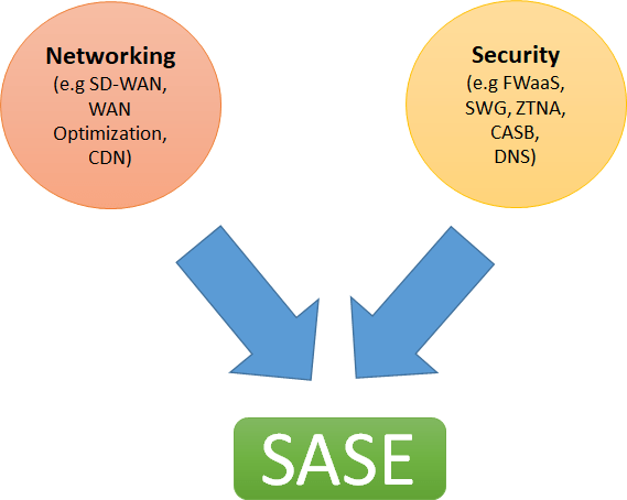
SASE is a technology that combines comprehensive WAN features with network security functions to support businesses’ dynamic and secure access needs. In the simplest terms, it has emerged with the combination of networking and security. According to the MEF document, it is defined as a service that connects users to applications in the cloud and provides connection performance and security assurance, with specified policies. SASE provides agility, flexibility, and adaptability in the areas where it is used.
As the traditional connections for security checks, connections must pass through the data center. However, the data center is no longer the center of applications and the applications used by businesses are starting to move to the cloud. In addition, shifting the center of security applications from the data center to the branches is not offered as a practical and scalable solution. It results in complex and costly security hardware at the endpoint. Adding more devices to branches (NGFW, IPS, IDS) makes the task of the relevant teams more complex for maintenance and troubleshooting.
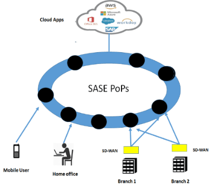
The latency to be experienced during access is very important for applications that are moved to the cloud. Also, distributed services are delivered closer to users to optimize latency and user experience with the SASE solution. The SASE cloud is implemented as a distributed cloud platform. Thus, the cloud that users want to connect to is not found in a single point. When the user wants to access the application, they are directed to the cloud with the least density. SASE acts as a kind of gateway, with traffic diverting from the cloud to applications used elsewhere. However, for a user who wants to remotely connect to applications from another country, for example, the traffic will still have to go to the center for security checks. This also increases the delay time and results in longer paths.
One of the most important concepts in SASE is that it is Identity oriented. Every user in SASE has an identity, a contact, an application service, or a device. SASE simplifies the authentication process by enforcing appropriate policies for the relevant resources the user is searching for. In this way, an identity-based, changeable and dynamic security policy set can be created. This provides a very powerful and rich security service that can be applied to users of the SASE Cloud. All heavy processing happens in the cloud. A unified network and security application are used, where network and security teams can manage all features and policies through a single interface. Thus, the monitoring, control, and management of the system are also easily achieved.
SDN and 5G
The diversity of access infrastructures and different service levels used in mobile networks make it difficult to use SDN, NFV, NV, or SDR (Software Defined Radio) applications in these networks. Users’ high data rate demands make resource management in these networks even more difficult. New challenges arise in the management of resources used for network virtualization solutions, mobility management, and quality of service. These problems such as the increase in network density and the availability of different spectrum bands, the optimal allocation of radio resources, interference suppression, and load balancing between network cells with 5G Technology create difficult processes in network usage. The flexibility offered by NFV provides an important opportunity for RAN (Radio Access Network) virtualization. However, the availability of high-performance platforms is important for the targeted competitiveness in 5G networks.
SD-RAN (Software Defined Radio Access Network) is an SDN technology. Just as a WAN solution is created in SD-WAN technology, it is an alternative solution for mobile communication using radio frequencies. Thanks to SD-RAN, the Control Plane and the Data Plane are separated from each other, allowing the development of innovative software solutions for RAN, regardless of infrastructure. These solutions allow software-based remote control for RAN, centralized management of radio resources. Thanks to these applications, internet service providers and mobile communication operators can easily access all network technologies, radio units, and base stations, providing better quality service and effective management on the network.
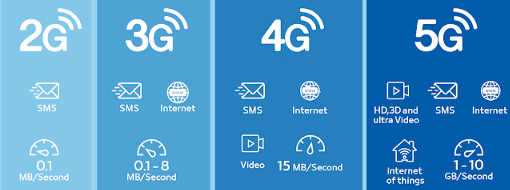
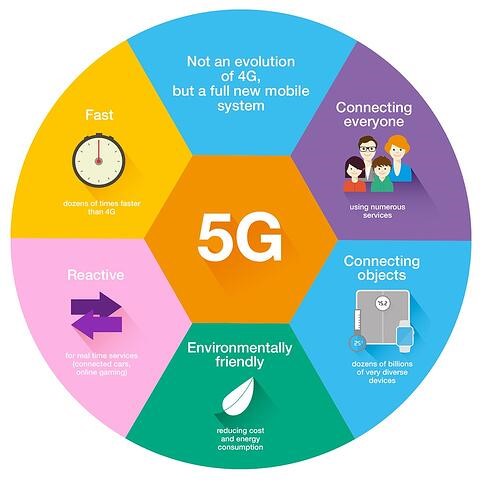
Mobile networks have continued to develop since 1991. 4G LTE in use today will focus on delivering mobile broadband services much faster than the 3G spectrum used in past years, while 5G will be a unified, more capable platform that will not only elevate mobile broadband experiences but also support new services such as mission-critical communications and massive IoT designed in such away.
5G is the 5th generation mobile network technology and is expected to play a much larger role than previous generations. It will not only be possible to connect people with the use of mobile networks, but also to provide a controllable service by connecting machines, objects, and all smart devices. This will deliver unprecedented levels of performance and efficiency in user experiences. High speed, ultra-low latency, greater bandwidth, and a uniform user experience will also come with this performance experience. At this stage, the 5G operating principle has a wide spectrum, starting from the low bands below 1 GHz to the mid bands up to 6 GHz and the high bands known as millimeter waves. It makes the most of every bit of spectrum at the available spectrum modifier bandwidth values.
Considering the main idea of SDN technology, the Control Plane is removed from the network hardware and the endpoints are controlled through a programmable logical software called a controller. The programmability of an SDN network with a 5G service enables new business models, facilitates the use of cloud technologies, and supports the growth of businesses that use it. Thanks to 5G, all services offered with SDN work faster, with high performance, high efficiency, and compatibility. Virtual networks can then be customized to meet the needs of applications, services, devices, customers, or operators.
Thanks to Polar Coding developed by Prof. Dr. Erdal Arıkan, 5G has become the standard for mobile technology. Prof. Dr. Erdal Arıkan’s “Polar Coding” study, which he published in 2008 after 20 years of academic studies, was implemented with 5G technology 10 years later.
Polar Coding is a method called channel polarization to generate code sequences for any data pair, which obtains the symmetric capacity of the packet input in the discrete and memoryless bands. When the number of repetitions increases in transmission, virtual channels tend to have either high reliability or low reliability (i.e. they become polarized), and data bits are transmitted to more reliable channels. Symmetrical capacity is the highest rate that can be achieved due to equal use of the channel’s input lines and is equal to the total transmission capacity if the channel has certain symmetry properties. Channel polarization refers to the fact that it is possible to synthesize from N independent copies of a given set of different N binary input channels so that the transmission capacities of the second set are very close to each other except for a negligible part. This second group of N channels is well deployed for channel encoding. Codes with this performance can be encoded and decoded within complexity 0. In October 2016, Huawei gave for channel coding for using Prof. Dr. Erdal Arıkan’s polar codes, he announced that 27Gbps was achieved in 5G field trial tests.
One of the biggest architects in the development and emergence of 5G technology, Bilkent University Electrical and Electronics Engineering Prof. Dr. Erdal Arıkan talks about 5G technology in an interview with the following words;
Prof. Dr. Erdal Arıkan: Mobile communication, one of the leading wireless communication systems, works according to certain international standards. 5G technology is the next generation communication standard. 5G technology provides faster data transfer and video communication compared to the 4G standard used today. Thanks to the high speed provided, virtual and augmented reality applications allow it to become widespread in communication systems. In summary, 5G technology is expected to meet the internet infrastructure need for next-generation engineering systems called cyber and physical systems.
In communication systems such as mobile phones, messages such as voice, data, and images are sent over the air as electromagnetic waves. Other effects in the air can cause the transmitted signal to deteriorate. This phenomenon is called “noise”. In communication engineering, there are various methods of transmitting the signal without noise and without error. These are generally called error-correcting coding methods. Polar coding is one such method. An example of error-correcting coding can be given from daily life: When transferring an important word to the other party, if you encode the letters of the word with city names, you will minimize the possibility of error. In most communication systems, messages are encoded by such methods and protected against noise. Polar coding is one of the two main error-correcting coding methods used in the 5G standard. The distinguishing feature of polar coding is that it can reach theoretical limits called the Shannon capacity limit. The Shannon limit is one of the fundamental laws of communications engineering that determines the maximum speed at which a message can be transmitted over a noisy channel. If you try to transfer data quickly above the Shannon limit, you will inevitably make mistakes. If you are willing to stay below the Shannon limit, it becomes possible to protect data against noise with error-correcting methods. Polar coding is a method that provides secure communication at any speed below the Shannon limit.
It allowed the Shannon limit threshold, which dictates the amount of data that can be sent with zero errors at a given bandwidth, to be exceeded. In addition to solving this 60-year-old problem, polar codes also enable a simpler design. All this means an increase in service quality. It provides the most reliable and least latency transfer of data transfer.
REFERENCES
- SDN – https://sdn.systemsapproach.org/intro.html
- OpenFlow – https://projet.liris.cnrs.fr/imagine/pub/proceedings/ICIP-2011/papers/1569408917.pdf
- OpenFlow – https://docplayer.net/13510885-Openflow-switching-data-plane-performance.html
- OpenFlow -https://techhub.hpe.com/eginfolib/networking/docs/switches/12500/59984929_openflow_cr/content/378345569.html
- OpenFlow – https://www.sciencedirect.com/topics/computer-science/openflow-protocol
- OpenFlow – https://opennetworking.org/wp-content/uploads/2014/10/openflow-spec-v1.3.2.pdf
- OpenFlow – https://www.section.io/engineering-education/openflow-sdn/
- Overlay Management Protocol – https://journey2theccie.wordpress.com/2020/04/23/cisco-sd-wan-omp/
- Overlay Management Protocol – https://www.networkacademy.io/ccie-enterprise/sdwan/omp-overview
- SD-WAN – Versa Networks
- CPE – https://telcocloudbridge.com/blog/sd-wan-vs-ucpe-vs-vcpe-the-simple-guide/
- Overlay / Underlay – https://telcocloudbridge.com/blog/overlay-vs-underlay-networks/
- Overlay / Underlay – https://www.networkacademy.io/ccie-enterprise/sdwan/underlay-vs-overlay-routing
- VxLAN – https://www.linkedin.com/pulse/overlay-network-vxlan-ve-sdn-taha-ergin/?originalSubdomain=tr
- SASE – MEF70 Documentation
- SDN ve 5G – Aselsan Dergi 5G ve SDF