Transformator
The transformer is used to measure and control the level of voltage or current in alternating current circuits. The incoming current or voltage can be stepped down or amplified depending on the type of transformer. While the change made on the voltage or current values is carried out by the magnetic field effect, there is no frequency change in the energy. For this reason, it can also be used as a circuit supply element in the systems where it is used.
Transformers are used quite frequently in power distribution and power transmission. Transformers play a major role in the transport of energy with the least loss along the way it leaves the power plant and reaches the houses. Power losses in power lines during transmission can be tolerated by transformers. By keeping the power coefficient and power value constant, transmission can be achieved by creating less loss with energy with low current value but high voltage value.
Transformers consist of primary and secondary conductors wound close to each other on a magnetic skeleton by their structure. Current or voltage values can be controlled depending on the winding ratio between the primary and secondary of the conductors. At this stage, there is no transmission between the primary and secondary windings over any conductor. Raising and lowering operations take place with the help of the magnetic field effect formed on the magnetic skeleton.

The alternating voltage applied to the primary winding creates a magnetic field on the magnetic skeleton. The secondary winding on the same skeleton is affected by the magnetic field created by the primary winding. Thus, an alternating voltage is also induced on the secondary winding. Induction is the creation of an electric current by the action of a magnetic field in a closed circuit placed in a changing magnetic field.
Low levels of energy loss occur during the operation of transformers. These energy losses occur through the magnetic skeleton material (copper, iron) used, due to the energy converted into heat, due to electrical resistance, or due to temporary magnetization (magnetization) that may occur.
Current Transformer

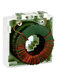
Current is the instantaneous level at which pieces of electrical charge carried by electrons pass through a conductive point in the electrical circuit. Current transformers are used for two main purposes in electrical systems, to measure current and to protect the system from high current. It is not possible to measure the current with high values coming from the power line with precision measuring instruments. After a certain level, it becomes difficult to measure current. In case the measurements cannot be made using sensitive measuring devices, current transformers can be used to measure the incoming and outgoing current. The primary windings of the current transformer consist of thick wires with as sparse winding as possible.
The value of the incoming current and the value of the outgoing current can be controlled, depending on the primary winding and secondary winding structure. The current transformer is connected in series to the circuits it will operate and works only with AC. The high current that comes into the circuit can be reduced to the desired level, suitable for the circuit structure, after passing over the current transformer. The incoming current is minimized and thus provides the necessary isolation for measurement. This prevents circuit damage due to high current. Thanks to the reduced current level, how much ampere the system uses in total can be displayed instantly. In the same way, the current values that come into the circuit or fluctuate can be increased in accordance with the usage and circuit structure, and their transmission can be ensured.
Voltage Transformer
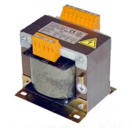
Voltage is the potential energy difference between the two ends of the conductor as a result of the electrostatic force that electrons in a conductive material are exposed to. Voltage transformers are used for two main purposes in electrical systems to measure voltage and to protect the system from high voltage. It is not possible to measure the voltage with high values coming from the power line by means of measuring instruments. After a certain level, it becomes difficult to measure voltage. In case the measurements cannot be made using sensitive measuring devices, voltage transformers are used to measure the incoming and outgoing voltage. The primary winding of the voltage transformer, unlike the current transformer, consists of tightly wound thin wires.
The value of the incoming current and the value of the outgoing current can be controlled, depending on the primary winding and secondary winding structure. The voltage transformer is connected in parallel to the circuits it will operate and can work with AC or DC. One end of the voltage transformers must be grounded to protect the system from high voltages. The high voltage that comes into the circuit can be reduced to the desired level according to the circuit structure after passing over the current transformer. The incoming voltage is reduced to a minimum, thus providing the necessary isolation for measurement. This prevents circuit damage due to high voltage. Thanks to the reduced voltage level, how much volts the system uses in total can be displayed instantly. Likewise, voltage values that come into play or fluctuate can be increased and transmitted in accordance with the usage and circuit structure.
3-Phase
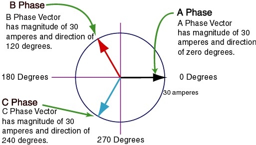
A single-phase electrical system is often used in areas that need to run small loads, for example in homes and simple systems. More precisely, the electricity, which is carried in three phases over the main lines, is used by reducing it in the electrical panels of the apartments in such a way that a single phase is distributed to the apartments. Three-phase electricity is an electrical supply system used in systems that need high power. It is generally preferred in industry or industrial areas. Electric vehicle charging stations, which are frequently used today, also provide energy with three phases. In single-phase electrical systems, the power line consists of a live terminal and a neutral terminal, while in three-phase electrical systems, there are three live terminals and a neutral terminal. These phases are called “R-S-T” or “U-V-W” or “X-Y-Z” or “A-B-C” phases. For these three live ends, there is a phase angle of 120° between each live end. The phase angle is the main factor determining the voltage between phases. The sum of the currents flowing through the three phases is always zero (0).
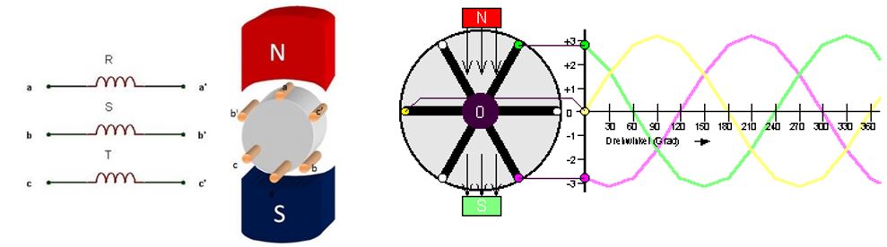
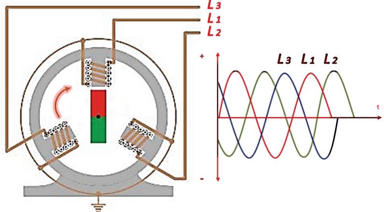
Three-phase systems consist of three main coils placed in a magnetic field. A common end of the three live ends is bridged and a neutral line is formed. Used to produce the same electrical power, 3-phase alternators are smaller and lighter than single-phase alternators. This also provides a cost advantage. The alternator is an electromagnetic device that converts mechanical energy into alternating current. In addition, motors operate much more efficiently under 3-phase energy supplies.
The ground line, on the other hand, is located independently of the live and neutral terminals in 3-Phase or Single-Phase operating power lines. Grounding is the connection of all conductive parts that are not directly connected to the energy, that is, not on the voltage line, to a metal driven into the ground. Thus, any static current that may occur on the devices or any leakage current that may occur in the system will be directly transmitted to the ground with low resistance.
Power lines can be checked with the help of a simple multimeter. When 3-phase power lines need to be controlled, the voltage value between any phase and neutral conductor should be between 220 and 230 Volts. Similarly, the measurements to be made between the phase and earth conductor must be between 220 and 230 Volts. These values are equal to the voltage value used in a single phase. The measurement between neutral and earth conductors should not exceed 1-2 Volts.
In addition, the instantaneous power is not constant in single-phase systems. Due to the sinusoidal form of AC systems, the power in single-phase systems varies in sinusoidal form. This causes vibration in single-phase motors, but in three-phase systems, the instantaneous power is always the same. As a result, it results in the most efficient state in terms of transmission and cost. In addition, the use of three-phase electricity can extend the life of electricity-generating systems.
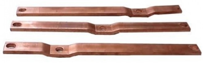
It must be transported to the panels with the help of large copper busbars for the distribution of three phases from the power line. In the use of copper, the current carrying capacity of copper busbars is important. To find the current resistance value of copper, the cross-sectional area formula of the conductor is used. The reason for using copper is only the price-performance ratio. 3-phase connection methods are used to transmit the current going to the panel to the motors to be connected to the panel.
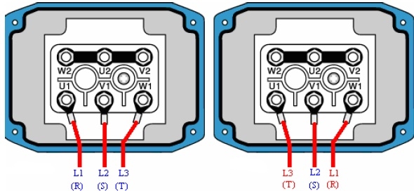
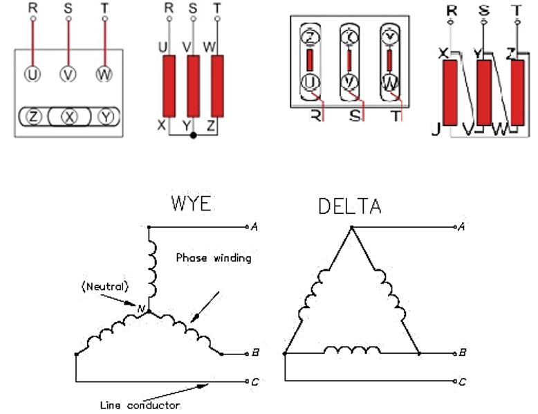
3-phase connection methods are used for better operation of motors in panel construction. There are two different types of 3-phase connection methods; “Delta” connection and “WYE” connection. When the motors start to work, they start to draw more current than their normal values. Excessive current draw of the motor causes deformation of protection line elements such as relay, motor protection switch, fuse, or switch. In order to prevent this situation and protect the motor, first WYE connection and then delta connection are applied.
In delta connection, the line voltage is equal to the phase voltage, and a voltage equivalent to the voltage in the network is applied to the receiver. In a delta-connected load, there is no neutral conductor. In WYE connections the current in the line is equal to the phase current, in the delta connection, the current in the line is equal to three times the phase current. In star connection, mains voltage is supplied to the receiving terminals, and other terminals are short-circuited. In the star connection load, there is a natural conductor at the common point of the phases. Thus, the amount of insulation is lower in star connections and higher insulation is required in delta connection. Star and delta connections can be converted to each other depending on the usage area and the required system.