STP (Spanning Tree Protocol) is the IEEE 802.1 standard. It is a protocol discovered to prevent loops that may occur during the communication of switches in the network with each other. However, it not only avoids loops but also chooses the best path for data transmission to take place. It runs on Layer 2 of the OSI Reference Model.
Loop formation is likely in large topologies where redundancy is of great importance and there are many physical connections on router devices. Availability of redundant lines is not guaranteed in networks that do not use the Spanning Tree Protocol. With STP, the lines become redundant, endless loop formation is prevented, and when the active link is interrupted, the redundant path becomes active.
When packets with unknown source and destination addresses arrive at the switch, they are flooded so that the destination can be found. A flood is an event that a packet whose source and the destination address are unknown is transmitted to the connected devices over all the interfaces connected to the device on the device. The fact that the sent packet cannot find its owner and is repeatedly transmitted to the same devices creates an endless loop. Packets entering a loop cause a problem called Broadcast Storm in the network. A broadcast storm is a situation where each port of the switch broadcasts its own broadcast frame and causes the resources in the network to be consumed. Thus, bandwidth is occupied and the network becomes unusable.
Loop formation is also inevitable in structures where more than one cable is connected between two switches and there is no Etherchannel. This cycle continues incrementally until the device is turned off. The loop can cause the device to shut down. The problem disappears for a short time until a new loop occurs, as the old packets that cause the loop will be lost on the devices that are turned off.
STP in Layer 2 communications, TTL value in Layer 3 IPv4 communications and Hop Limit in Layer 3 IPv6 communications can prevent loop occurrences. Ethernet packet headers do not have a TTL value. The TTL (Time to Live) value is a mechanism that limits the lifetime of data transmitted on the network. For packets with TTL value in the packet header, the TTL value decreases one by one as packet transmission between router devices is provided. When the TTL value is reset, the packet is dropped and considered as packet loss. A packet transmitted from one device to another router device skips a hop. Hop count indicates how many different points a packet passes through during transmission. In IPv6 communications, when a certain number of transmissions, that is, the hop limit is exceeded, or the same packet is repeatedly sent to the same device, the packet is dropped again and is considered lost.
In Cisco brand switches, the STP feature is active by default, and some ports are automatically blocked to prevent endless loops that may occur. Switches send BPDU (Bridge Protocol Data Unit) messages to each other in order to discover the loops and communicate with each other. The BPDU package contains information such as Bridge ID, MAC address, Port ID.

Features that are of low value usually win in Layer 2 calculations, while features that have high value in Layer 3 calculations. For this reason, the device with the lowest Bridge ID value is assigned as Root Bridge in the environment. For Bridge ID calculations, the priority values of the devices are compared first, and if the priority values are the same, a comparison is made between the MAC addresses. The device with the smaller MAC Address is selected as the Root Bridge.
Additionally, Convergence Time is the time it takes for the STP to start working and when all elections and appointments are completed. At the end of this process, Root Bridge is selected and the ports are either suitable for transmission or are blocked. Data communication cannot be performed during the Convergence Time.
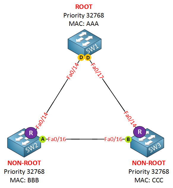
Root Bridge: In networks running STP, a device Root Bridge is selected in the network according to the STP algorithm. Root Bridge is the reference point selected by the STP algorithm and the leading router device to prevent endless loop formation in the network. On the Root Bridge selected device, BPDU messages are started to be collected from all switches in the network. The states of the ports are determined by the BPDU messages to be collected and distributed.
Initially, all devices identify themselves as Root Bridge and start sending BPDU messages to all connected devices. Bridge ID is included in the content of the transmitted BPDU message. Bridge ID contains the “Priority” value and “MAC” address of the router device.
” Bridge ID (BID) = Priority + MAC Address “
The device with a low Bridge ID is eligible to become a Root Bridge. So the switch with the lower priority becomes the Root Bridge. If the priority values are not configured manually, the priority values of devices from the same manufacturer usually have the same value as each other. For devices with equal priority values, MAC addresses are compared in the next step. Root Bridge is selected for the switch with the lowest numeric MAC address. The device selected as Root Bridge starts sending Superior BPDU.
Root Port: Root Port is the first reference point in the packet forwarding of the Root Bridge, which has been selected to prevent infinite loop formation. Generally, Root Bridge is assigned from the low-cost uplink ports on the devices closest to the selected device or on the devices it is directly connected to. Because the ports that receive the Superior BPDU packet must be assigned as Root Ports.
In addition, the cost value comes to the fore in Root Port selection. Cost is the calculation of the overall cost that will be spent traveling from one point to another. Bandwidth, number of hops, and all similar conditions affect the cost value. High bandwidth means low cost. In other words, the one with a high bandwidth value (low-cost value) wins. When choosing a Root Port, 3 criteria are considered:
-Low Cumulative Cost
-Low Upstream BID
-Low Port ID
Designated Port: All ports on the Root Bridge selected by STP are labeled as Designated Port to prevent infinite loop formation. A new elimination algorithm is started for the ports other than the Root Port. The paths to the Root Bridge are examined and the ports with the lowest cost are called Designated Ports. Because the ports that send the Superior BPDU packet must be Designated Ports. Root Bridge’s ports can never be Blocked.
Blocked Port: While selecting the Designated Port, the port with the highest cost is assigned as the Blocked Port. The Blocked Port remains in a blocked (down) state unless there is any change to prevent the infinite loop. Ports other than Designated Port and Root Port, which may cause an infinite loop, are labeled as blocked ports.
Alternate Port: Alternate Port acts as a kind of blocked port. While selecting the Designated Port, they wait in the Alternate Port status during the selection. It is a backup for the Root Port. Port types that are blocked in RSTP but have special cases are labeled as Alternate Ports.
Edge Port: There is an additional port definition called Edge Port. End ports are ports that connect to devices such as computers, servers. Therefore, Edge Port does not participate in STP calculations. Edge Port does not receive BPDU packets.
Backup Port: Backup Port is types that are blocked in RSTP are labeled as Backup Port. In other words, it is the spare port.
NOTE: Any Designated Port is broken, canceled, etc. In such cases, an STP calculation is made again and new Designated Ports are determined after choosing between the additional ports. In case of a crack in the topology, the system will re-make the STP calculations each time, and other choices may occur each time. Thanks to some commands to be written under the port, the system can be fixed. Because every time Root Bridge, Root Port, etc. It’s not something you want to change. These commands are mentioned below:
- Uplink-Fast → Uplink Fast is the algorithm for Cisco that works in the 802.1D standard. Ports to the Root Bridge are never blocked. Provides alternative paths for root bridge before Root Port failure. When the Root Port is down, the secondary link with a low cost is immediately activated after the Root Port.
- Port Fast → Port Fast command Convergence time is reduced, thereby increasing the speed of accessing network resources. However, any switch can be plugged into this port and corrupt the STP calculations.
- BPDU Guard → Port-Fast enabled port will break STP calculations. By means of BPDU Guard, when a BPDU packet arrives at the Port-Fast enabled port, the port is closed automatically. For this reason, after activating Port-Fast, the BPDU guard must be activated so that STP accounts are not corrupted.
- Root Guard → After entering the root guard command on the Designated Ports on the Root Switch, no switch can be root again. Because Root Switch does TCN (Topology Change Notification).
- Loop Guard → Used for software errors. If the port on which this command is applied is supposed to receive BPDU packets, if it stops receiving BPDU packets, the port will enter the Inconsistence state rather than the Forwarding State. It remains in the Inconsistence state until it receives the BPDU packet again.
- UDLD (Unidirectional Link Detection) → If the mutually sent Hello packets cannot be transmitted, there may be a problem on Layer 1. It is used for hardware errors that may occur in the physical layer, it can only be used on ports with fiber connections. Since it is structurally different from Loop Guard, it should be used with Loop Guard. It works in two different modes, Normal and Aggressive. If Hello packets are not received in normal mode, the port becomes Undetermined. If Hello packets cannot be received in aggressive mode, the port becomes Error-Disabled.
STP TYPES
1. STP (SPANNING TREE PROTOCOL)
STP is the IEEE 802.1D industry standard. It is the first protocol developed to prevent infinite loop occurrences. The convergence time of STP is about 50 seconds. The transactions that took place during this period are as follows:
In case of any interruption in the Root Port, route calculation is needed to select the Root Port again. The transition time of the port from the Block state to the Listening (Listen State) is 20 seconds, the transition time from listening to learning (Learning State) is 15 seconds, and the transition time from learning to forwarding is 15 seconds on average. Thus, there is an average calculation time of 50 seconds. No device can perform data communication during this period. It is not a desirable situation in networks where time-sensitive, critical applications are running. It is ensured that all VLANs are used with a single “instance”.
| Forwarding -> RP and DP communication starts. |
| Learning -> All information is learned by bridges. |
| Listening -> Root bridge, root port is selected. |
| Blocking -> BPDU message traffic but no communication. |
| Disabled -> Each port is initially disabled. |
2. RSTP (RAPID SPANNING TREE PROTOCOL)
RSTP is the IEEE 802.1W standard. RSTP operation works similarly to STP. Unlike STP, the operations it performs during its operation and the time to complete these operations (convergence time) are much less than STP. It has been developed for use in topologies where the processing time cannot be tolerated and it is desired to be less than 50 seconds. Route calculations made in STP are performed in 5 steps, while route calculations made in RSTP are performed in 3 steps. So it works faster than STP. Working principle Unlike STP, instead of blocking a port, discarding (destroying) operation is used. Port mode may appear as Block, but this port is Alternate Root Port. In case of any malfunction on the Root Port, the Designated Port is activated.The operations that take place during the operation of RSTP are as follows:
| Forwarding-> Communication starts. |
| Learning-> STP Learning+ STP Listening. |
| Discarding -> BPDU message traffic starts. |

3. MSTP (MULTIPLE SPANNING TREE PROTOCOL)
MSTP is the IEEE 802.1S standard. It works like RSTP, the computation time (convergence time) is much shorter compared to STP. But while port blocking is performed in RSTP, port blocking is not performed in MSTP. In MSTP, instances are created for specific VLAN groups. All calculations for operations occurring during operation are made on an instance basis with more than one VLAN. It provides different VLAN transitions from each link it is connected to. Specially configured “instance” values are used for a particular group of VLANs. It is generally preferred in VPLS structures. Thus, “Load Balance” is provided. However, different STP instances can use their own topology independently of other instances.
4. PVST (PER VLAN SPANNING TREE PROTOCOL)
PVST is the protocol developed by Cisco in which STP is run separately by creating a separate “instance” for each VLAN. It is often confused with MSTP. But in PVST, an instance is created for each VLAN. In MSTP, an instance is created for multiple VLAN groups. Thus, thanks to PVST, a more scalable topology can be obtained as there will be a separate instance for each VLAN.
Clinton Esota
10 October 2024 — 04:49
Amazing topic thank you so much Emré!