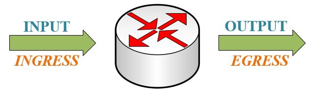
Layer 3 devices (Layer3 Switch or Router) do “Forwarding” for packet transmission. Forwarding refers to how the router device in the network determines the best path to forward the incoming packet.
Each router makes its decision about packet forwarding based on the information on its routing table. The router has certain information in its routing table does not mean that other routers have the same information. In addition, the forwarding information about the forwarding path of the packet to be transmitted from one network to another network does not contain any forwarding information about the return path of the packet.
Forwarding consists of three different structures that are independent of each other. These are;
- Routing
- Switching (Load-Balancing Methods)
- Encapsulation
Switching is the process of forwarding the packet received from one interface of the router to a different interface of the same router. Routing, due to its working nature, is the provision of IP addresses for devices on different networks to communicate with each other, which way they will use. Encapsulation, on the other hand, helps to protect the transmission by keeping the packet and packet headers of the data to be transmitted and limiting its access.
Packet switching methods are used in IP packet forwarding from OSI layers over Layer 3. These methods are also known as “Layer 3 Load-Balance” methods. One of the main responsibilities in packet transmission is to encapsulate the packets to be transmitted in accordance with the data link. The more efficiently this process is performed by the routing device, the faster the packet transmission rate will increase. The first technique for routers developed over time and became used today. During this time, more scalable, faster, efficient communication and cache-based methods have been developed. The improvements ensure that packets can be transmitted without noticeable delay. 3 different packet transmission techniques are used in order to realize efficient and fast communication.
1. Process Switching
Process Switching is one of the oldest and most powerful packets switching techniques. The processor of the router is directly involved in the forwarding decisions of the packets. At this stage, the processor’s responsible for processing the packet to be transmitted, determining the appropriate time for transmission, choosing the interface to which it will be transmitted, and programming the correct operation of the transmission process. In the Process Switching structure, all packets must pass through the processor.

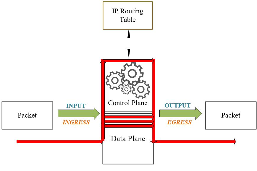
Operations are to be applied to the packet are performed by the processor of the routing device. The processor, in other words, CPU (Central Processing Unit). The processor is located in the Control Plane in terms of its location. Control Plane can forward outgoing IP packets to the Data Plane or use its own routing mechanism to determine the next-hop IP address. The packets of the data to be transmitted are processed on the processor independently of each other. Even if the destination is the same for multiple packet streams of the same data, this process is applied one by one for each packet.
In addition, in case of problems, the processor can solve the problem on the packet to be transmitted by performing mathematical calculations. Therefore, it allows load sharing between unused connections and provides stability in the network.
Operations on the processor begin with the packet arriving from the interface to the router and transmitted to the processor. Packets transmitted to the processor are read and stored in memory. The scan process is performed to check the routing table for the destination IP address of the packet. Depending on the result of the scan, the TTL value is decreased in the packet header and the CRC values on the IP header are controlled, recalculated, and updated. Then, the IP address on the destination (next-hop) is found and the interface that provides access to the next-hop address through the router is determined by the physical layer header. The identified information is processed on the packet header to assist transmission to the destination. After this applied process, the ARP table is checked and all the information required for the next-hop transmission is written on the physical layer header. Encapsulation is performed in accordance with the data connection, and the packet is made ready for transmission in line with all the information.
Also, there are some disadvantages to Process Switching. Since each packet is processed individually, CPU usage increases, which will create problems especially in networks with heavy traffic. In addition, packets coming over multiple interfaces are transmitted to the processor in no particular order. Transmitting the packets to the processor without a specific order will cause the target device receiving the packets to put the packets in the correct order with the help of a buffer or its own processor at the end of the transmission. Thus, the target devices will have to do more processing in transmission, and both CPU usage will increase and time losses will occur. This situation will reduce the transmission performance.
2. Fast Switching
The router needs to handle more packets on the processor in high-traffic builds. In the Fast Switching method, which has been developed to make the process more practical and efficient, only the first packet of the data to be transmitted is transmitted to the processor. All remaining packets after the first packet go through the Data Plane without visiting the processor. Thus, less load is placed on the CPU.
In Fast Switching technology, the address and next-hop information of the incoming package are copied and saved. A temporary cache is used to store information and guarantee fast transmission. The first packet of the same data to be transmitted is transmitted over the processor. Using the CPU and Routing Table, the required information is calculated once and stored in the cache until the data transmission is complete. Thus, it is not necessary to calculate regularly for other packets of the same data. The remaining packets are transmitted by referencing the information stored on the router’s cache, without CPU intervention by visiting the Control Plane. If the incoming packet does not have the same data as the previous packet, the mathematical operations are calculated again using the CPU and the Routing Table and are temporarily stored in the fast cache. This operation is performed for each of the packet groups transmitted for independent data.
3. CEF Switching (Cisco Express Forwarding)
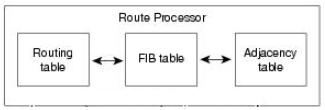
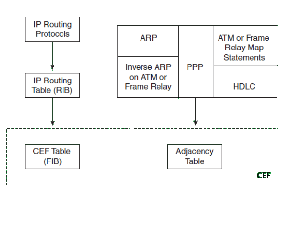
Due to the developing network structure and packet transmissions in large structures where the traffic has a complex structure, CEF (Cisco Express Forwarding), is occurred the newest packet switching technology. It provides users with enhanced performance, scalability, and consistency. It is used by default on routers since CEF occured. The structure is similar to the cache storage structure used in Fast Switching. Processes are implemented in CEF through FIB (Forwarding Information Base) and Neighborhood Table (Adjency Table).

Using CEF ensures that, less processor load occurs, each line used works at full capacity and high efficiency. In addition, in networks with a constantly changing structure, the routing tables always change. CEF can handle that issue via using updates. Also, it prevents traffic density and high processor usage caused by changes. In addition, CEF solves the most probable problems in advance.
FIB (Routing Information Base) works with the same logic as the Routing Table in terms of its general structure. CEF copies the routing table to the Routing Knowledge Base (FIB). Thus, the same address information that the routing table needs to forward packets is kept in the FIB. Address changes in the routing table are simultaneously reflected in the FIB table. The difference between them is that while all route information is kept in the routing table, unused route information is not kept in the FIB table. For this reason, a much faster search is performed and faster results are obtained compared to the Routing Table.
Devices connected to each other via a single link are called neighbor devices. The Neighborhood Table used in CEF contains the Layer 2 MAC address information of interconnected devices in the network. The neighborhood table is created with reference to the ARP Table.
If other tables have to be checked due to any problem that may arise during transmission or an unknown route transmission, the CEF table must be recreated as it is corrupted. The CEF table must be rebuilt so that the FIB and Neighborhood Table are also rebuilt. At this stage, there may be changes in the processing process due to certain packets transmitted to the processor of the router device. These packages are; Applies to ARP, PPP, ICMP, TTL, MTU, DHCP, Route Update, CDP, NAT packets or packets not found on FIB or belonging to different CEF variants. The table will be recreated for the information not found on the CEF Table. The change to be experienced in the process may change with new calculations to be made on the processor. However, packets do not visit the processor in any way.
NOTE: When the debug command is run, all packets passing through the router should be able to be examined. Since the packets do not pass through the CPU, the command “#no ip route-cache” is entered. Thus, Fast Switching and CEF Switching are disabled, Process Switching is enabled and all packets are routed through the CPU. Thus, transit traffic can be observed. If changes in the routing table occur too quickly, the percentage of packets processed by Fast Switching becomes too low and the caching mechanism is ineffective. In addition, in high-traffic networks, RAM starts to support the processor. RAM usage increases, CPU usage decreases. In this case, the amount of RAM required for the device used also increases.
NOTE: In addition, when going into details, there are two different structures in “CEF”, namely Software Based CEF and Hardware-Based CEF.
Software-Based CEF, also known as sCEF (Software CEF), consists of two different elements. The first of these is the FIB and the second is the Neighborhood Table. All packets that will pass through the Data Plane without visiting the Control Plane are controlled and transmitted via tables. The software CEF’s role is only to update the hardware CEF and control packet forwarding.
Since Packet Switching operations are performed on hardware, Hardware-Based CEF, also known as hCEF (Hardware CEF), is a much more effective method. It works faster and with higher efficiency. On the basis of hardware, CEF is divided into Accelerated CEF (aCEF-Accelerated CEF), Centralized CEF Mode (Centralized CEF Mode) and Distributed CEF Mode (dCEF-Distributed CEF Mode) depending on its working structure.
Information such as MAC addresses, Routing Table, or Access Lists are stored in CAM (Content Addressable Memory) and TCAM. While the CAM table is used to store Layer 2 information, the TCAM table combines the upper layer information into a single table, in summary, allowing routing decisions to be taken much faster.
When using hardware-based CEF, decisions are often made using the TCAM table so that routers can make faster routing decisions. TCAM, Ternany Content Address Memory. While TCAM is being formed, it uses multiple tables so that the router can make quick decisions. Thus; FIB is created based on the details available for the Neighborhood Table, Access List, and QoS.
- When the routing decision is on the Router Processor, all routing decisions are made by the RP. This is central routing. In Centralized CEF mode, the FIB and Neighborhood Table used for CEF are located on the Route Processor, ie Control Plane. So the processor performs express forwarding. Centralized CEF mode is generally used when line cards are not suitable for CEF. To enable it, the command “R1(config)#ip cef“ is used.
- When Distributed CEF is enabled, when routing decisions are separated from the RP and placed in line cards, routing decision is made via line cards and route related transactions are not transmitted to the router processor. An identical copy of the FIB and the Neighborhood Chart is kept in line cards. Packet redirects are performed by looking for identical copies. Thus, the load on the processor is reduced. dCEF uses the IPC (Inter-Process Communication) mechanism to keep the copied tables kept on the processor up to date and correct. To enable it, the command “R1(config)#ip cef distributed“ is used. While some of the line cards on the same router support CEF, some may not. In this case, the line card that does not support dCEF is forced to forward packets to the processor for forwarding.
Rejeki Betz
14 April 2025 — 19:49
Great insights, Emre! I found the explanation of different Layer 3 forwarding techniques very enlightening. It’s interesting to see how each method has its own advantages and use cases. Looking forward to more posts on similar topics!
Fastwin Network
1 April 2025 — 20:30
Great insights on Layer 3 forwarding techniques, Emre! I especially appreciated your breakdown of the different methods and their applications. It really helped clarify some concepts I was struggling with. Looking forward to more posts like this!
NULLS BRAWL
24 January 2025 — 14:21
Great insights on Layer 3 forwarding techniques, Emre! I especially appreciated the detailed explanation of how these methods can enhance network efficiency. Looking forward to implementing some of these strategies in my own projects!
Ashe Clark
5 November 2024 — 20:32
Great insights on Layer 3 forwarding techniques, Emre! I especially appreciated the breakdown of different protocols and their use cases. It really clarified some concepts I was struggling with. Looking forward to more posts like this!