Virtual LAN, or VLAN, is the concept of separating the local network into virtual areas. It is located in the second layer of OSI layers. It is approved by IEEE and is known as the IEEE 802.1Q label in the Ethernet packet header.
With VLAN technology, devices and resources on a local network are separated so that they are logically isolated from each other. Each of the virtual network groups isolated from each other creates a special broadcast domain for itself. One of the biggest advantages of establishing a virtual subnet is that it reduces the possibility of broadcast packets in traffic conflicting with each other. Since each VLAN will communicate only with its own broadcast packets after VLAN configuration, broadcast traffic is reduced and bandwidth is increased. In this way, additional devices or investments to be used in the network structure can be saved. Additionally, dividing the network into separate segments using VLAN technology allows end devices to be managed more easily. Management of relevant VLANs can be facilitated by using an ACL structure on the switch or by writing rules on the Firewall.
Areas where broadcast packets are likely to conflict with each other are called Collision Domains. A higher number of Collision Domains means fewer devices can communicate directly with each other. Thus, each VLAN also creates a Broadcast Domain within itself. The fewer devices are divided into more different zones, the better communication can be established. Using VLAN increases the number of collision domains, thus reducing the rate of collisions that may occur in traffic.
In order to broadcast within itself, each VLAN sends data only with a packet header belonging to its own VLAN. This situation is called VLAN tagging. Thus, every device that is not in the same VLAN drops this packet, thinking that this packet does not belong to it.
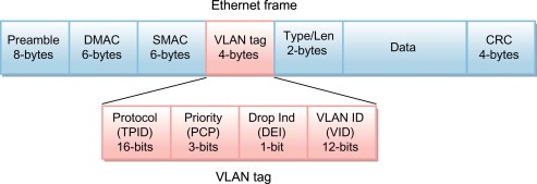
The size of the packet header containing VLAN information is determined as 4 Bytes. The maximum number of VLANs available within the same network is 4096. There is a 12-bit VLAN ID Header in the VLAN packet header. The labeling method in VLAN packet headers can also be done using “ISL”, but since the ISL header is 30 bytes, the “802.1q” structure works much faster.
One of the factors to consider when configuring VLAN is the port status. Whether the port is access, trunk, or hybrid means determining the broadcast domains that will communicate.
- Access Link is a connection that belongs to only a single VLAN. Two devices connected to each other via Access Link can communicate with each other over the same VLAN because they are connected to a single broadcast group, independent of the physical network. Packets sent by devices on the access link cannot communicate with devices outside their VLANs unless they are directed by a router or another layer 3 device.
- The data is transmitted independently of the VLAN tag with Trunk Link. Thus, data can be transferred from one VLAN to another VLAN. If you want to communicate with two different VLANs, a Trunk Link must be used between them. Trunk Port provides transmission as “tagged”, that is, the packet header is tagged. In this case, it can be thought that a label, a patch, or a sticker has been pasted on the VLAN ID tag in the package header, indicating that this ID will be made irrelevant.
However, if two different VLANs will communicate, Inter VLAN Routing must be done through a router. Thus, VLAN tags are sent to a Router in their current form without any structural damage on the packet header. The router makes the transmission mechanism and addressing decision depending on the tag. Communication is provided in a healthier and safer manner.
- In a hybrid port, multiple VLANs can communicate with each other. A single port can be used as both Access and Trunk thanks to the hybrid port.
Additionally, contrary to popular belief, there are 2 default VLANs in switches, these are VLAN1 and VLAN1005. Native VLAN carries traffic untagged. Before a VLAN is established, the switch “VTP” or “Vlan Transparent” mode must be on. When VTP Transparent mode is on, only VTP Advertisement information is received from the trunk port of the device.
Native VLAN is used to send untagged traffic assigned to the trunk port and sent to trunk ports. The trunk port directs traffic not coming from any VLAN to the Native VLAN. Each trunk contains a Native VLAN and by default, this is VLAN 1. Native VLAN must be identical for all devices, in case of mismatch it will cause problems in transmission.
Management VLAN can be any VLAN configured to manage the device. If no special VLAN is configured as the management VLAN, VLAN 1 serves as the management VLAN, as in Native.
VxLAN
VxLAN, which works in a similar structure but is a more advanced and new technology, has a packet header size of 8 Bytes. 16 million different VxLAN areas can be created with VxLAN technology. It works by tunneling VLAN technology. It provides service by encapsulating the Layer2 Ethernet packet header within the Layer4 UDP packet header. Thus, the physical network merges with the virtual network and the data in the cloud becomes available for use as if it were local. Virtual connections in the network are created through virtual tunneling called VTEP. VTEP provides communication. In this way, traffic can be controlled and a safe way of communication is provided. In order to better understand the VxLAN structure, you can access the article I wrote about Underlay and Overlay in the SDN article on my profile.
